HVAC SYSTEMS VRF / VRV – VARIABLE REFRIGERANT FLOW
Before you design, learn what universities, building owners, energy managers, consultant and installers have learned through their experience with VRF systems.
With this guide you will learn more about Variable refrigerant flow (VRF), also known as variable refrigerant volume (VRV), an HVAC technology that like ductless minisplits uses refrigerant as the cooling and heating medium. This refrigerant is conditioned by a single outdoor condensing unit, and is circulated within the building to multiple indoor units.
VRF system introduction
VRF systems generally include one or more air-source outdoor compressor units serving multiple indoor fan coil refrigerant evaporator units. This type of system is distinguished from small split systems that usually serve a maximum of five indoor units without variable refrigerant flow.
VRFs Outdoor Units typically are equipped with a DC inverter compressor to support variable motor speed and therefore variable refrigerant flow rather than simply turning on / off operations. In this configuration VRF units operate only at the necessary speed, allowing considerable energy savings in partial load conditions. VRF heat recovery technology allows individual indoor units to operate in heating or cooling mode independently as needed, while the compressor load benefits from internal heat recovery.
Primary manufacturers:
-
- JAPANESE: Daikin, Panasonic, Mitsubishi Electric, Mitsubishi Heavy Industries, Fujitsu General, Johnson Controls-Hitachi, Toshiba, Yanmar (GHP)
-
- KOREAN: LG, Samsung
-
- CHHINESE: Gree, Haier, Hisense, Midea
-
- AMERICAN: Carrier, York International, Trane, Lennox
-
- EUROPEAN: Bosch
How much energy can you save with VRF?
After contributing to the transformation of the environmental air conditioning, VRF systems (Variable Refrigerant Flow systems) are now able to guarantee efficient and competitive solutions for the majority HVAC applications.
VRF use a fluid called refrigerant as the cooling and heating medium instead of water. This refrigerant is conditioned by a single outdoor condensing unit and is circulated through the system within the building via a compressor to multiple indoor units.
These systems are easy to install and allow to preserve the structure of the existing building. The modular design makes them a great option for projects that will be built in stages, for example, one hotel floor at a time without interrupting the whole business activity.
It is the task of the external condensing unit to dispose of or integrate the power necessary for the operation of the cycle, exchanging heat with the external environment.
The whole system uses one or more inverter compressors to move the refrigerant and adjust the flow of refrigerant accordingly to current load.
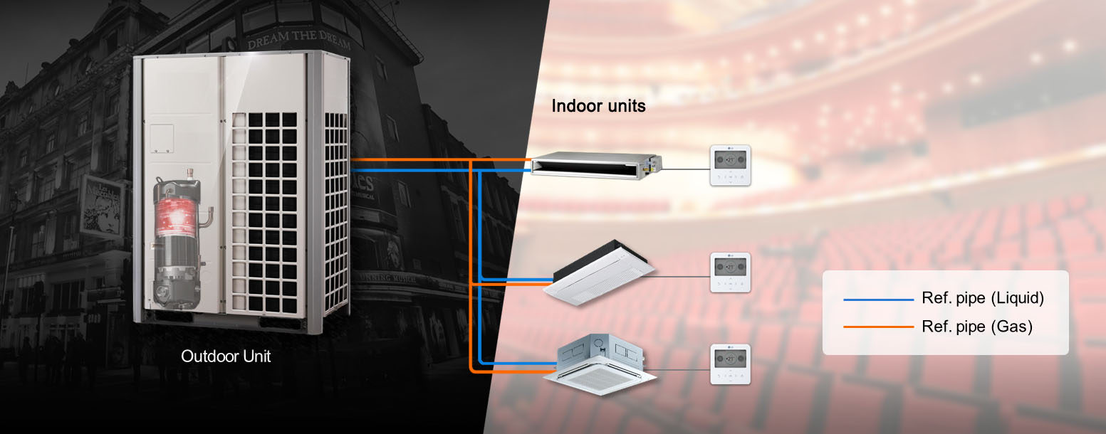
The most basic version of a VRF system uses an outside condenser unit that can be used for either heating or cooling. There are two refrigerant lines, one for supply and one for return, and they are shared by various indoor fan-coils.
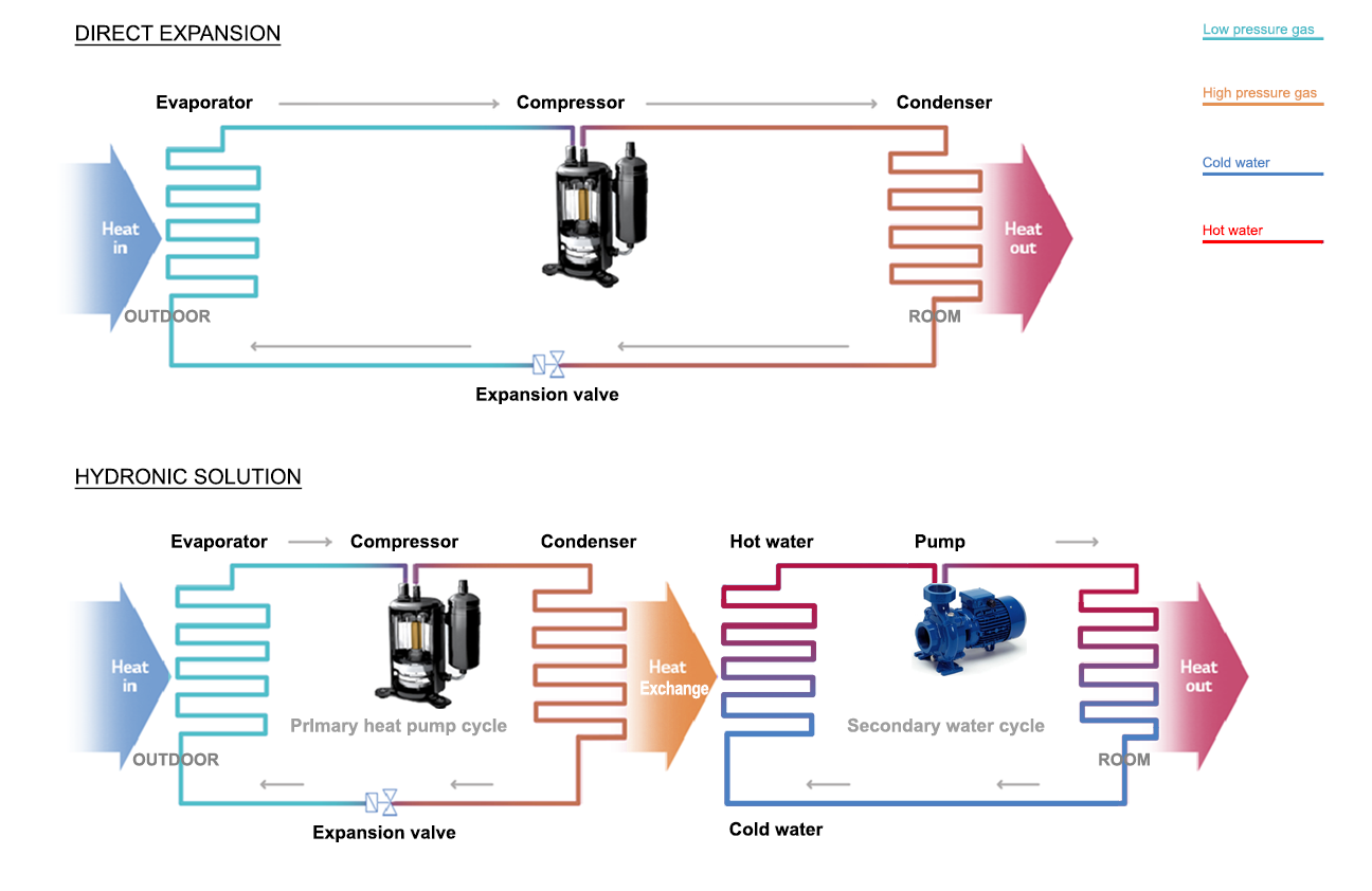
In DX systems the intermediate water fluid is eliminated
It is possible to identify two main reasons that explain why the direct expansion solution is more efficient than the hydronic solution:
- the hydronic solution uses a refrigerant-water heat exchanger whose efficiency is way below 100%. With DX solution the entropy generation and the exergy destruction at the refrigerant-water heat exchanger are cut out;
- In a hydronic system the refrigerant does not give heat directly to the environment but gives it to the water which, in turn, must give it to the environment. This means that the heat pump must also work with higher temperatures (pressures) as it does not directly transfer heat to the air in the environment, but must release heat to the water which in turn releases it to the environment.
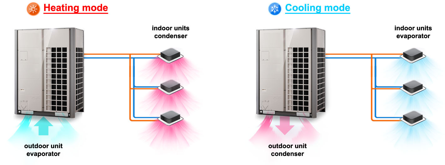
Depending on the operating mode, the outdoor unit and indoor units may behave as a condenser or evaporator.
In winter (heating mode) the outdoor unit behave as an evaporator and the indoor units as a condenser. In summer (cooling mode) the outdoor unit behaves as a condenser and the indoor units as an evaporator.
With refrigerant flowing directly into indoor units, is it possible to achieve higher nominal and seasonal coefficients of performance (COP, EER, SCOP, SEER) than air to water heat pumps. Usually performances are certified by third party testing based on well-defined procedures that ensures a healthy and solid competition on a market open to all manufacturers. AHRI and Eurovent are two independent companies famous for their strict test measures and high standards.
The VRF systems are able to operate in heating mode, in cooling mode and with the possibility of being configured for heat recovery. Heat Recovery systems have the ability to simultaneously heat certain zones while cooling others. In this case the heat extracted from zones requiring cooling is put to use in the zones requiring heating. This is made possible because the heating unit is functioning as a condenser, providing sub-cooled liquid back into the line that is being used for cooling. While the heat recovery system has a greater initial cost, it allows for better zoned thermal control of a building and overall greater efficiencies.
For further information on energy saving read the full documents
- Directory – VRF AHRI efficiency certifications
- Directory – VRF Eurovent efficiency certifications
- Variable Refrigerant Flow – Wikipedia
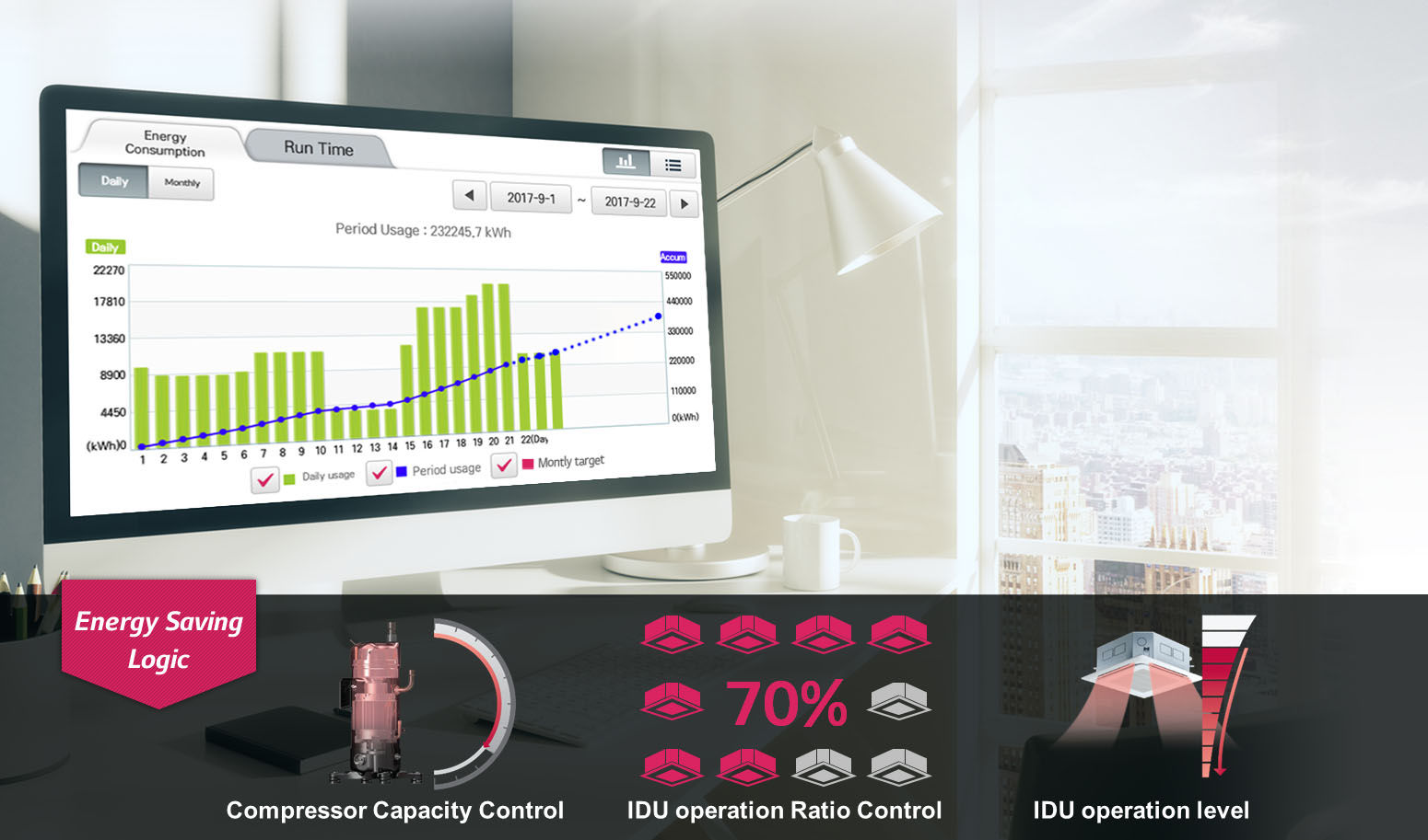
What impact does the VRF have on energy consumption?
VRF systems have a significant impact on energy consumption.
Main VRF advantages:
-
- part-load operation
-
- zoning capabilities
-
- heat-recovery potential
-
- inverter-duty compressors
Thanks to its advanced technology, ultra-precise control and the absence of intermediate water fluid it is possible to achieve higher nominal and seasonal coefficients of performance (COP, EER, SCOP, SEER) than air to water heat pumps.
The VRF systems are able to operate in heating mode, in cooling mode and with the possibility of being configured for heat recovery. Heat Recovery systems have the ability to simultaneously heat certain zones while cooling others. In this case the heat extracted from zones requiring cooling is put to use in the zones requiring heating. This is made possible because the heating indoor unit is functioning as a condenser, providing sub-cooled liquid back into the line that is being used for cooling.
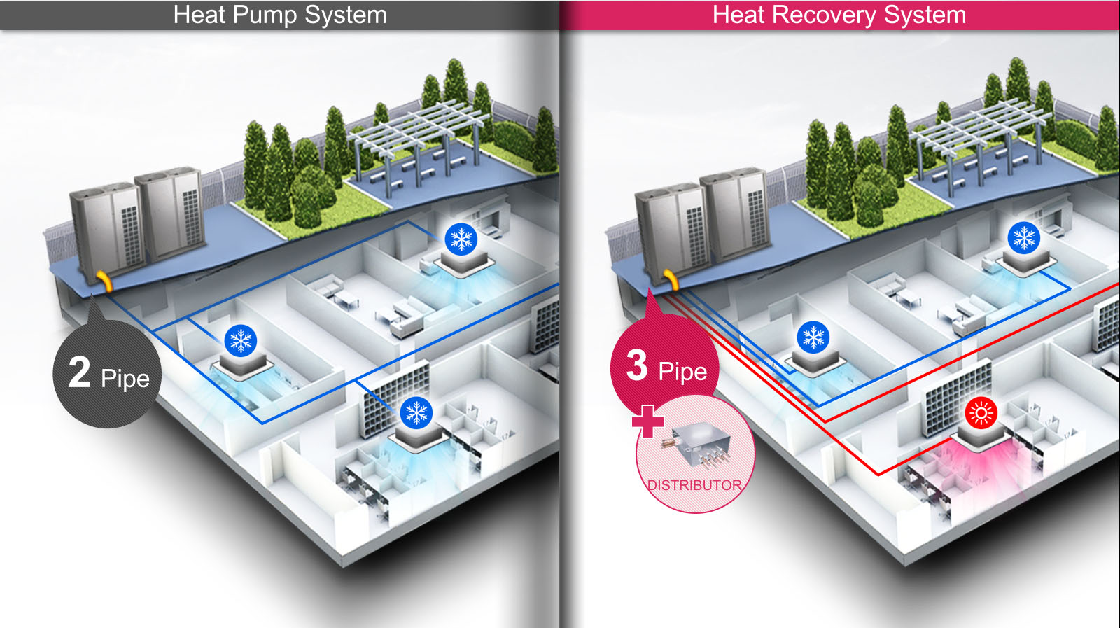
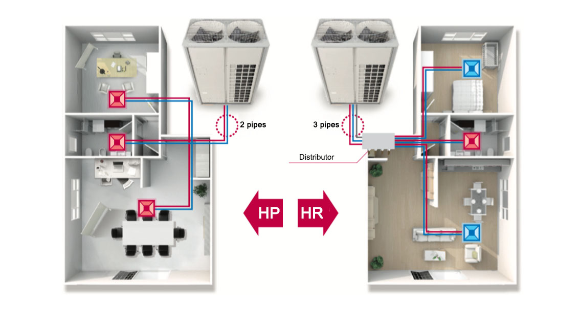
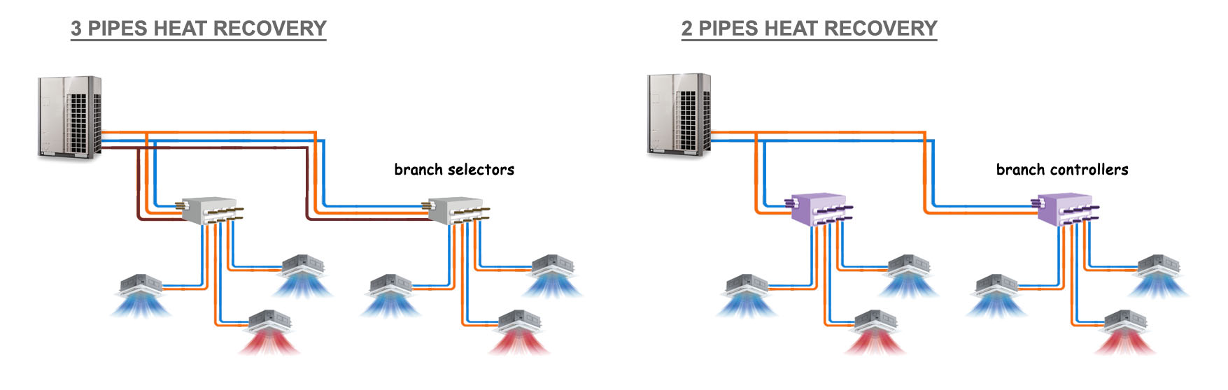
This is usually done through a three pipes design (hot gas fot reating, liquid for cooling and and return) and one or more distributors (branch selectors) with valves that switch the supply depending on the operating mode required by the indoor unit.
Only few brands are able to do this with a two pipes system using a branch controller. In this case the heat recovery between indoor units is carried out in the BC boxes which houses a liquid/gas separator, allowing the outdoor unit to deliver a mixture (2 phase) of hot gas for heating and liquid for cooling, all through the same pipe.
While a two-pipe system allows a reduction of pipe transmission losses and installation costs, a three-pipe system generally provides a higher heat recovery efficiency than a two-pipe system.
While the heat recovery system has a greater initial cost, it allows for better zoned thermal control of a building and overall greater efficiencies.
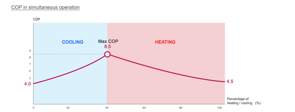
If the (COP) coefficient of performance in cooling mode of a system is 4, and the coefficient of performance in heating mode is 4.5, then heat recovery performance can reach more than 8.5.
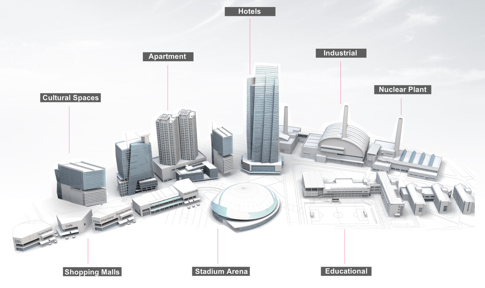
A state-of-the-art HVAC technology, Variable Refrigerant Flow zoning systems are highly beneficial in all areas of commercial construction because they provide precise zoned control that can contribute points toward LEED® certifications.
Developed by the U.S. Green Building Council (USGBC), LEED provides building owners and operators a concise framework for identifying and implementing practical and measurable green building design, construction, operations and maintenance solutions.
Thanks to VRF high performances and cutting-edge technology it is possible to achieve a great number of points in LEED Energy and Atmosphere Credit.
Thanks to VRF high performances and cutting-edge technology it is possible to achieve a great number of points in LEED Energy and Atmosphere Credit.
ENERGY & ATMOSPHERE (EA)
PREREQUISITES:
-
- Fundamental Commissioning & Verification: VRF manufacturers can offer technical assistance before and during system installation and assist with startup, commissioning of equipment and control systems
-
- Minimum Energy Performance: VRF systems are incorporated in ASHRAE Std. 90.1-2010 and AHRI 1230 established testing method for VRF technology
- Fundamental Refrigerant Management: VRF systems do not use chlorofluorocarbon (CFC)-based refrigerants in HVAC&R systems
For further information on energy efficiency read the full documents:
- Coefficient of performance – Wikipedia
- LEED – Wikipedia
- Directory – VRF Eurovent efficiency certifications
- Directory – VRF AHRI efficiency certifications
Refrigerant and Safety
VRF systems distribute refrigerant throughout the building offering flexible installation.
VRF systems use refrigerant R-410A. The safety classification of R-410A in ASHRAE Standard 34 is group A1: nontoxic and nonflammable refrigerant with zero ozone-depletion potential. Safe, clean and environment friendly. it meets the stringent mandates of both the Montreal Protocol and the U.S. Environmental Protection Agency.
Even if R-410a belongs to A1 group, the American and European regulations says that VRV Systems have to be properly selected and designed adhering to ASHRAE Safety Standard 15, and Standard 34.
However, due to the ability to displace oxygen, VRV Systems have to be properly selected and designed adhering to ASHRAE Safety Standard 15 & 34 (U.S. Territory) and UNI EN 378 (European Territory).
ASHRAE Standard 15 & 34 (U.S. Territory)
ASHRAE Standard 34 sets the refrigerant concentration limits used in ASHRAE Standard 15 calculations. The refrigerant concentration limit (RCL) is used to determine the allowable pounds of refrigerant per 1,000 cubic feet of occupied space. An occupied space is defined as “…that portion of the premises accessible to or occupied by people, excluding machinery rooms.”
The RCL for R410a is 25 lbs/1,000 cubic feet. This amount is reduced by 50% for all areas of institutional occupancies and some 24 hour a day occupancies (13 lbs/1000 cubic feet).
UNI EN 378 (European Territory)
The UNI EN 378 – 2017 regulation specifies the requirements related to the safety of people and goods with regard to fixed and mobile refrigeration systems, including heat pumps. The regulation sets the refrigerant concentration limits for category A environments to the maximum practical limit of 0.44 kg/cubic meter of refrigerant content in environment in case a loss occurs.
Category A environments: rooms, parts of buildings, building where: people may sleep, people are restricted in their movement, an uncontrolled number of people are present or to which any person has access without being personally acquainted with the necessary safety precautions (ex. hospitals, courts or prisons, theatres, supermarkets, schools, lecture halls, hotels, restaurants…
Manufacturers support the professionals providing free tools the design VRF systems and to estimate amount of refrigerant contained in the overall system. Tools calculate the total amount of refrigerant contained in the designed system and compare it with the volume of the occupied spaces.
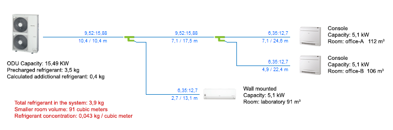
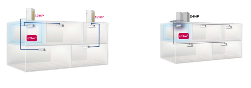
In order to comply with the limits imposed, various solutions can be adopted: dividing the system into several smaller systems, shortening the pipes, and increasing the volume of the rooms (for example putting in communications two rooms with transit grids or lifting the doors) are just some of the possibilities available.
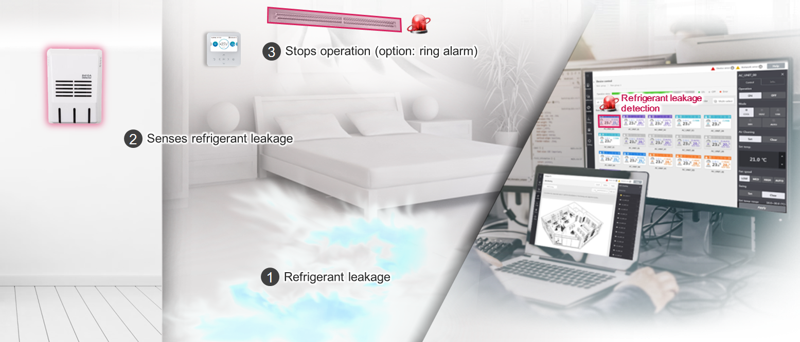
If it is not possible to be within the limits, there are still practical alternatives: some VRF manufacturers offer a sensor that detects refrigerant leaks and, when the concentration exceeds a certain concentration, not only stops the operation of the indoor unit, but also activates an audible and visual alarm, giving the occupants the chance to leave the room and ventilate the environment.
UNI EN 378 (European Territory)
- DOWNLOAD – ASHRAE 15-2016 (PACKAGED W/ 34-2016)
- DOWNLOAD – UNI EN 378 – 2017
Want to learn more about why VRF is the best solution for your building’s needs?
ASK FOR SUPPORT!
Energy engineer with a bachelor's degree in industrial engineering, a master's degree in Heating, Ventilating and Air Conditioning (HVAC) and a Master in Business Administration.